To engineer a reliable, heavy-duty drivetrain, one must first solve a fundamental problem of vehicle kinematics: cornering.
When an auto vehicle drives in a perfectly straight line, the left and right wheels rotate at the exact same speed. However, the moment the vehicle enters a turn, the dynamics change entirely. The outer wheel must travel a significantly longer arc—and therefore cover more ground—than the inner wheel. If the left and right wheels were locked together on a single solid axle, the tires would be forced to slip, scrub, and drag across the pavement. This would not only destroy the tires in a matter of days but also subject the axle shafts to catastrophic torsional stress, eventually snapping the metal.
This brings us to the most critical component in your axle assembly. We will discover the core mechanics behind the differentials, learn why your vehicle needs it, and exactly how it manages wheel speed.
What is an Auto Vehicle Differential?
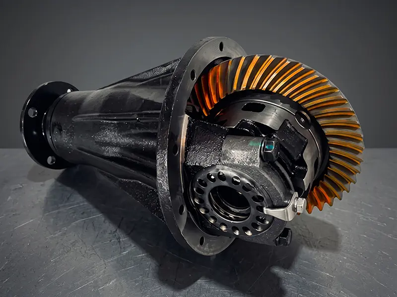
At its most basic engineering definition, an auto vehicle differential is a complex mechanical gear train located between the driven wheels. It serves three non-negotiable functions in a drivetrain:
- Power Redirection: It takes the rotational power (torque) coming from the transmission and driveshaft and redirects it 90 degrees to spin the left and right axles.
- Torque Multiplication: The final drive ratio (the ratio between the ring gear and the pinion gear) acts as the final gear reduction in the vehicle, multiplying torque before it hits the wheels.
- Wheel Speed Management: It independently manages wheel speed, allowing the left and right tires to rotate at different RPMs while still continuously delivering power to both.
The Core Mechanics: How It Manages Wheel Speed
To truly understand how it manages wheel speed, we must look inside the differential carrier (the housing that holds the internal gears) and examine the relationship between the Spider Gears (Pinion Mates) and the Side Gears.
The side gears are splined directly to the left and right axle shafts. The spider gears sit between them, meshing with both side gears simultaneously. The spider gears are mounted on a cross-pin that rotates with the main differential case.
Scenario 1: Driving in a Straight Line
When the vehicle is moving straight, there is equal traction and equal resistance on both the left and right tires. Because the resistance is equal, the spider gears inside the carrier do not rotate on their own axis. Instead, they act as solid wedges, locking the left and right side gears together. The entire differential carrier, the spider gears, and the side gears all rotate as one single, solid unit. Torque is split 50/50, and both wheels spin at the exact same speed.
Scenario 2: Entering a Corner
When the vehicle turns, the inner wheel encounters more resistance (because it is making a tighter turn), and the outer wheel requires more speed to cover the wider arc.
This difference in resistance forces the spider gears to start walking. While the entire differential carrier is still rotating forward, the spider gears begin to physically spin on their own cross-pin axis. As a spider gear spins, it allows the inner side gear to slow down, while simultaneously pushing the outer side gear to speed up.
Mathematically, the differential ensures that the average speed of the two wheels always equals the rotational speed of the differential carrier. If the carrier is spinning at 100 RPM, and the inner wheel drops to 90 RPM during a turn, the spider gears mechanically force the outer wheel to spin at 110 RPM. This is the mechanical brilliance of the open differential.
The Manufacturing Reality: Why Tolerances Matter
Understanding the theoretical mechanics of an auto vehicle differential is simple; manufacturing one that can survive a million miles of extreme commercial torque is entirely different.
When those spider gears and side gears mesh, they are transferring thousands of Newton-meters of torque across microscopic contact patches. If the involute profile of those gear teeth is machined poorly, or if the backlash (the gap between the meshing teeth) is too loose, the differential will suffer from “clunking” during acceleration and severe NVH (Noise, Vibration, and Harshness) at highway speeds.
For the differential to manage wheel speed seamlessly, the internal components must be manufactured to absolute Tier-1 OEM tolerances.
- Precision Forging and Machining: The spider and side gears must be precision-forged to ensure a continuous grain flow in the steel, maximizing sheer strength. After forging, the spherical thrust faces of the gears must be CNC-machined to exact concentricity. If the gears are eccentric, they will bind and gall against the carrier housing during a tight turn.
- Strict Backlash Control: In a standard open differential, the mesh between the spider and side gears must maintain a highly controlled backlash (typically around 0.10mm to 0.15mm, depending on the application). Too tight, and the gears will overheat and seize. Too loose, and the impact shock of sudden acceleration will sheer the teeth completely off.
- Metallurgical Integrity (Case Depth): The friction generated when the spider gears spin during cornering is immense. Standard unhardened steel would melt and fuse. Through continuous gas carburizing, Tier-1 manufacturers create an exact Effective Case Depth (ECD)—a glass-hard, wear-resistant outer shell over a tough, shock-absorbing ductile core.
Partner with True Drivetrain Experts
The auto vehicle differential is a masterclass in mechanical engineering. But a differential is only as reliable as the factory that cuts the steel.
Whether you are engineering a heavy-duty commercial axle or a compact, high-RPM EV reducer, the core mechanics dictate that there is zero room for error. At XiangYue OEM Differential & Gear Manufacturer, we do not just understand how wheel speed is managed; we manufacture the high-precision internal gear kits, ring and pinion sets, and machined carriers that make it happen.
Are you dealing with premature gear failure, excessive drivetrain noise, or inconsistent supplier quality? Bring your blueprints to a true Tier-1 manufacturing partner.
📧 Submit your CAD drawings or physical samples today for a comprehensive Design for Manufacturing (DFM) review and secure your drivetrain supply chain.

