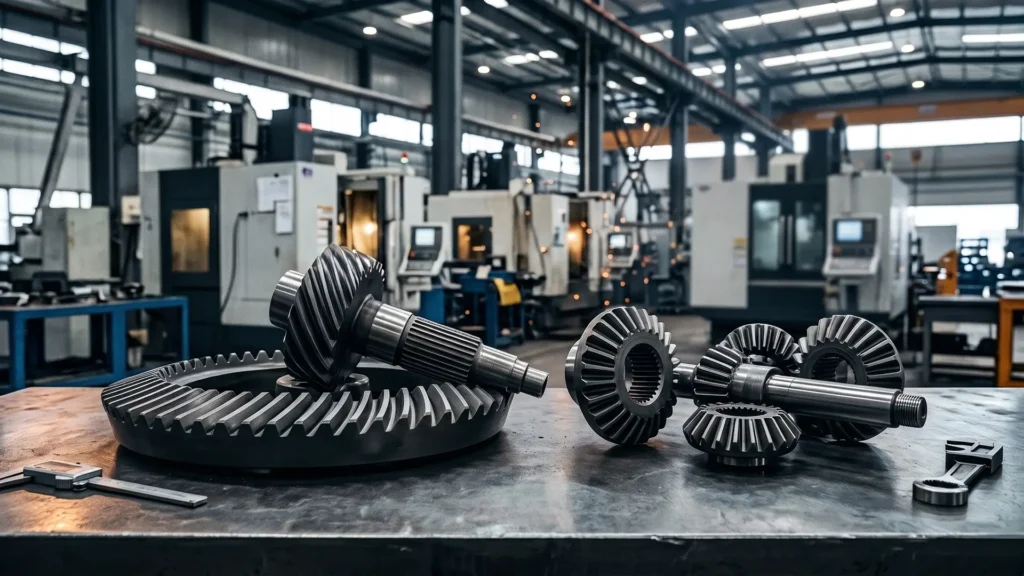

When outsourcing custom drivetrain components to a global manufacturing partner, chassis engineers and procurement managers consistently face a critical engineering pain point: the dangerous mismatch of international gear quality metrics. A North American OEM might submit a blueprint specifying a strict “AGMA Class 11” requirement, only to receive a quotation from an Asian or European Tier-1 facility guaranteeing “DIN Class 5” tolerances.
The immediate question arises: Are these equivalent? The definitive answer is that while they are comparable, they are not identical. The AGMA system historically uses a higher number to denote higher precision, whereas the DIN system uses a lower number for tighter tolerances. Assuming a direct 1:1 translation without understanding the underlying metrology and measurement methodologies will lead to one of two disastrous outcomes. Either the gear is under-engineered, resulting in catastrophic NVH (Noise, Vibration, and Harshness) failures and premature bearing fatigue; or the gear is over-engineered, forcing the buyer to pay massive NRE (Non-Recurring Engineering) premiums for aerospace-level profile grinding when a commercial hobbing process would have sufficed.
To secure a robust, cost-effective supply chain, mastering the nuances of AGMA vs DIN gear standards is non-negotiable. This comprehensive engineering guide decodes the technical differences between these prominent quality rating systems, maps their equivalencies, and explains the shop-floor CNC machining realities required to achieve these exact micro-geometry tolerances.
The Philosophical and Regional Divide
The debate over AGMA vs DIN gear standards is ultimately a conversation about regional engineering legacies, metric versus imperial measurement systems, and the evolution of global manufacturing.
The AGMA Legacy (American Gear Manufacturers Association)
For decades, the North American automotive, aerospace, and heavy industrial sectors relied exclusively on the AGMA 2000-A88 standard. In this legacy system, gear quality is rated on a scale typically ranging from Q5 to Q15. The core philosophy of the classic AGMA standard is that the higher the quality number, the tighter the tolerance and the more precise the gear.
For example, an AGMA Q6 gear is suitable for slow-moving agricultural machinery, while an AGMA Q12 or Q14 gear is reserved for high-RPM electric vehicle (EV) e-axles or turbine reduction boxes. However, recognizing the need to integrate with the global metric supply chain, AGMA released a newer standard: AGMA 2015-1-A01. This newer standard drastically shifted the paradigm to align with international ISO standards, changing the rating prefix to “A” (Accuracy Grade) and reversing the scale so that a lower number indicates higher precision (ranging from A2 to A11). Despite this update, the vast majority of legacy CAD drawings circulating in the North American supply chain still utilize the classic AGMA 2000-A88 Q-number system.
The DIN Standard (Deutsches Institut für Normung)
Conversely, the European and Asian manufacturing ecosystems—and the vast majority of global CNC machine tool builders—operate on the DIN 3962 standard (often used interchangeably with ISO 1328-1). The fundamental rule of DIN is the exact opposite of the classic AGMA standard: the lower the number, the higher the precision.
The DIN scale ranges from Class 1 (absolute master gears used for calibration, requiring extreme environmental control to manufacture) down to Class 12 (crude, cast gears with minimal machining). For heavy-duty commercial axles, high-torque reducers, and precision custom differentials, engineers generally operate within the DIN 4 to DIN 7 range.
The Metrology Parameters: What Are We Actually Measuring?
When engineers attempt to compare AGMA vs DIN gear standards without understanding the underlying metrology, they overlook how these tolerances physically impact gear meshing. Whether a CMM (Coordinate Measuring Machine) is outputting an AGMA report or a DIN report, the probe is inspecting the same critical micro-geometry parameters.
To bridge the gap between these standards, you must understand the four pillars of gear quality metrics:
1. Profile Deviation (Involute Error) The profile of a gear tooth is designed to be a perfect involute curve, allowing the meshing teeth to roll against each other with a constant velocity ratio. Profile deviation measures how far the actual machined tooth face deviates from this theoretical mathematical curve. If the profile error exceeds the allowable DIN or AGMA limits, the gears will not roll smoothly; they will micro-collide, generating transmission error (TE). This is the leading cause of high-frequency gear whine and severe NVH in custom differentials.
2. Lead Deviation (Helix Error) Lead deviation measures the accuracy of the gear tooth across its face width (axial direction). If the lead angle is machined incorrectly, the gears will suffer from “edge loading.” Instead of the heavy torque load being distributed evenly across the entire face of the gear, the force is concentrated on one small edge. This localized stress easily breaches the yield strength of the carburized steel case, leading to sub-surface spalling and rapid catastrophic failure.
3. Pitch Deviation (Single and Total Cumulative) Pitch is the theoretical distance between corresponding points on adjacent teeth. Single pitch deviation measures the error between two adjacent teeth, while total cumulative pitch deviation measures the maximum variance over the entire 360-degree rotation of the gear. High pitch errors cause torsional vibrations, acting like a microscopic hammer that beats against the drivetrain bearings thousands of times per minute at high RPMs.
4. Radial Runout Runout measures the concentricity of the gear teeth relative to the axis of rotation (the bearing bores). As discussed in advanced drivetrain engineering, absolute concentricity is critical. If radial runout is out of tolerance, the gear will rotate with an eccentric “wobble,” causing the backlash to continuously tighten and loosen during a single revolution.
The Equivalency Matrix: AGMA vs DIN
While a direct mathematical formula cannot perfectly convert every single micro-geometry parameter due to different inspection algorithms, the global gear manufacturing industry utilizes an accepted equivalency matrix.
This reference table maps the classic AGMA 2000-A88 standard to the modern DIN 3962 / ISO 1328 standard, providing procurement teams with a reliable translation mechanism for evaluating supplier capabilities.
| DIN 3962 / ISO 1328 | Classic AGMA 2000-A88 | Modern AGMA 2015-1-A01 | Typical Manufacturing Process Required | Common Drivetrain Application |
| DIN 2 – 3 | AGMA 14 – 15 | A2 – A3 | Aerospace-grade hard profile grinding in climate-controlled metrology labs. | Master calibration gears, aerospace turbines. |
| DIN 4 | AGMA 12 – 13 | A4 | Multi-axis CNC profile grinding (Hard-state finishing). | High-RPM EV e-axles, high-speed racing differentials. |
| DIN 5 – 6 | AGMA 10 – 11 | A5 – A6 | CNC profile grinding or ultra-precision gear honing post-heat treatment. | Tier-1 heavy-duty commercial axles, high-torque reducers, zero-NVH gear sets. |
| DIN 7 | AGMA 9 | A7 | Precision CNC hobbing followed by shaping or shaving (Soft-state finishing). | Standard industrial gearboxes, low-speed off-highway differentials. |
| DIN 8 – 9 | AGMA 7 – 8 | A8 – A9 | Standard CNC hobbing or milling (No finishing operations). | Agricultural equipment, hand-crank mechanisms, slow conveyor drives. |
| DIN 10 – 12 | AGMA 5 – 6 | A10 – A11 | Casting, forging, or crude broaching. | Non-critical kinematic mechanisms, heavy construction linkages. |
The Shop Floor Reality: Achieving High-Precision Grades
Evaluating AGMA vs DIN gear standards reveals that pushing a gear from a DIN 7 to a DIN 5 (or an AGMA 9 to an AGMA 11) is not merely a matter of adjusting the settings on a CNC machine. It requires an entirely different paradigm of manufacturing, tooling, and capital equipment.
The Limitation of Soft Machining (DIN 7 / AGMA 9)
Many lower-tier gear manufacturers rely entirely on CNC hobbing and milling. In the “soft state” (before the steel is hardened via heat treatment), a high-quality CNC hobbing machine can theoretically achieve a DIN 6 accuracy. However, drivetrain gears must undergo continuous carburizing and quenching to survive extreme torque.
As discussed in advanced metallurgy, heating 20CrMnTi or 8620H steel to 930°C and quenching it in oil fundamentally alters its molecular structure, releasing internal stresses that warp the metal. Even if a gear goes into the furnace as a DIN 6, it will emerge warped, often degrading to a DIN 8 or DIN 9. Therefore, a factory that only possesses hobbing machines cannot realistically guarantee anything tighter than a DIN 7 or AGMA 9 for a finished, hardened differential gear.
The Necessity of Hard-State Profile Grinding (DIN 4 – DIN 6 / AGMA 10 – 13)
To hit the rigorous tolerances required for heavy-duty commercial and EV drivetrains (DIN 5 or DIN 6), the manufacturer must employ post-heat treatment finishing.
Once the gear has been carburized and hardened to 58-62 HRC, it is mounted on a multi-axis CNC profile grinding center. Using specialized, diamond-dressed grinding wheels, the machine removes microscopic amounts of the hardened steel, physically erasing the heat-treatment distortion.
This process restores the involute profile, lead angle, and pitch spacing to extreme accuracy. Furthermore, CNC profile grinding allows Tier-1 engineers to apply “micro-geometry modifications”—such as tip relief, root blending, and crowning. These microscopic intentional deviations from a perfect involute curve are designed to compensate for the housing flex that occurs under extreme dynamic torque, ensuring the gears mesh silently under heavy loads. If your print demands a DIN 5 or AGMA 11 rating, CNC profile grinding is a non-negotiable manufacturing requirement.
Metrology and Validation: Proving the Standard
The final, and perhaps most critical, aspect of interpreting AGMA vs DIN gear standards is validation. A manufacturer can claim to produce AGMA 11 gears, but without the correct metrology infrastructure, that claim is mathematically meaningless.
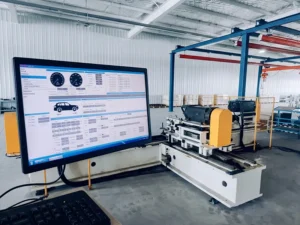
Standard micrometers, calipers, and optical comparators cannot verify DIN 5 tolerances. Verification requires dedicated gear inspection centers, such as Klingelnberg or Gleason analytical gear CMMs. These highly sensitive machines utilize tactile scanning probes to trace the gear teeth in three dimensions, capturing thousands of data points per second.
The software then compares the physical data against the mathematical CAD model, generating a comprehensive inspection report that explicitly grades the profile, lead, pitch, and runout deviations against the chosen AGMA or DIN algorithmic standards. When sourcing custom drivetrain components, procurement managers must demand these analytical inspection reports as part of the PPAP (Production Part Approval Process).
At XiangYue OEM Differential & Gear Manufacturer, we eliminate the ambiguity of cross-border sourcing. Our engineering team fluently translates between AGMA, DIN, and ISO specifications to perfectly align with your legacy blueprints. Equipped with state-of-the-art continuous carburizing furnaces, multi-axis CNC profile grinders, and analytical gear CMMs, we do not just promise tight tolerances—we mathematically prove them. Whether your drivetrain requires the rugged durability of a DIN 6 commercial axle or the zero-NVH precision of an AGMA 12 EV reducer, we deliver drop-in ready, absolute-concentricity gear assemblies designed to outlast the competition.
Submit your technical drawings today, and let our engineers provide a comprehensive Design for Manufacturing (DFM) review to secure your global supply chain.